|
Project 36: |
|
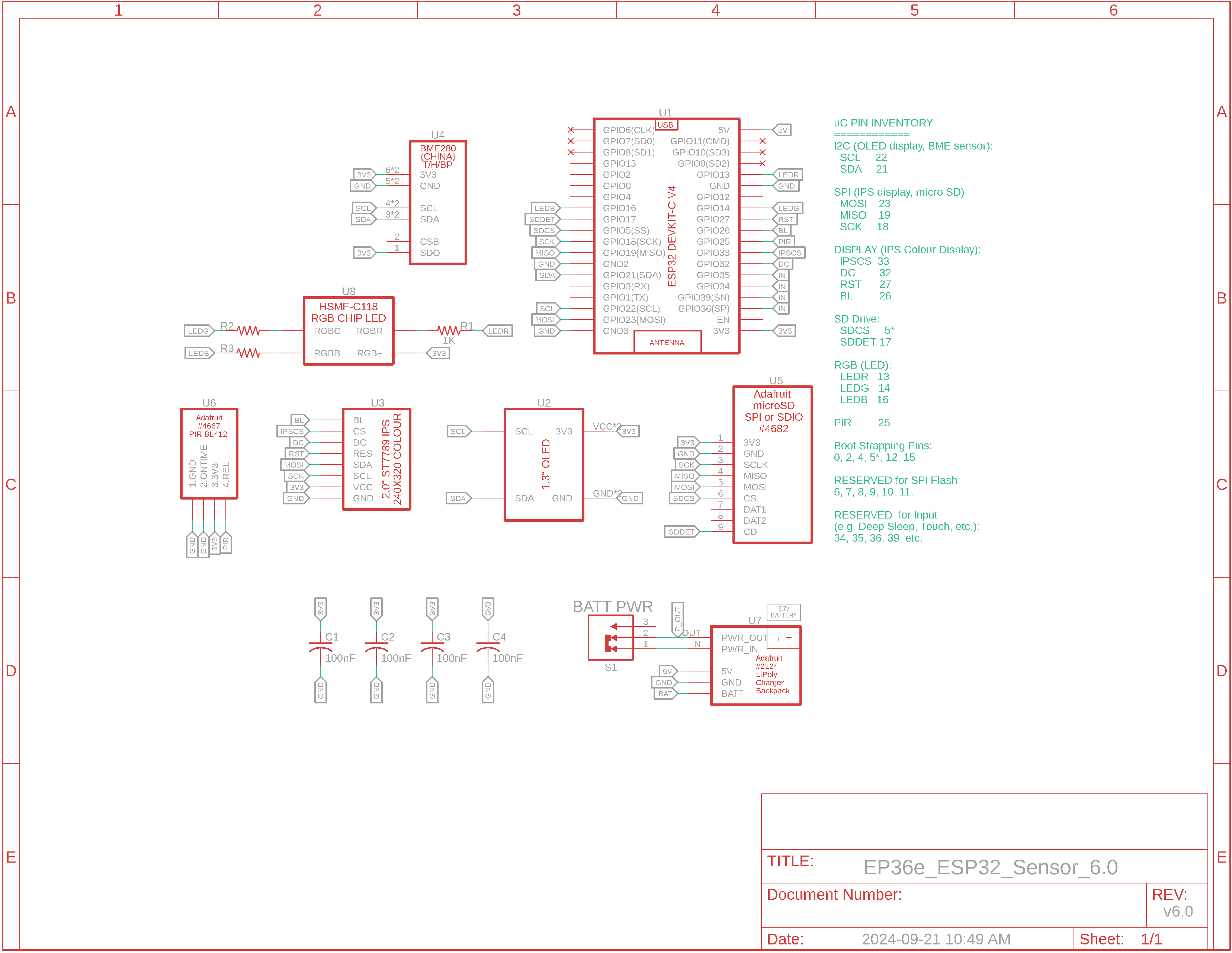
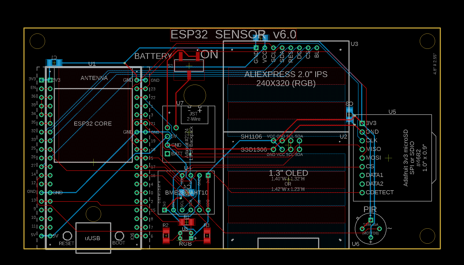
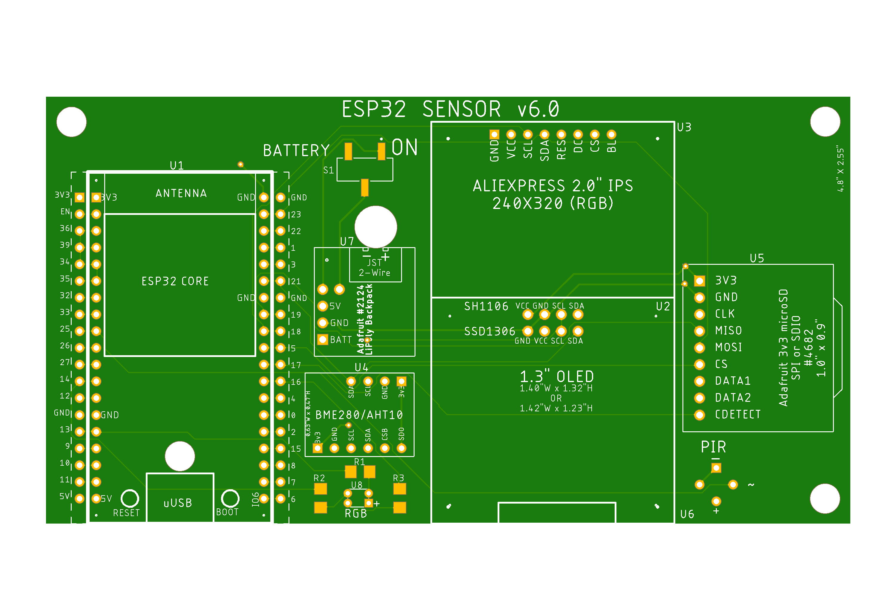
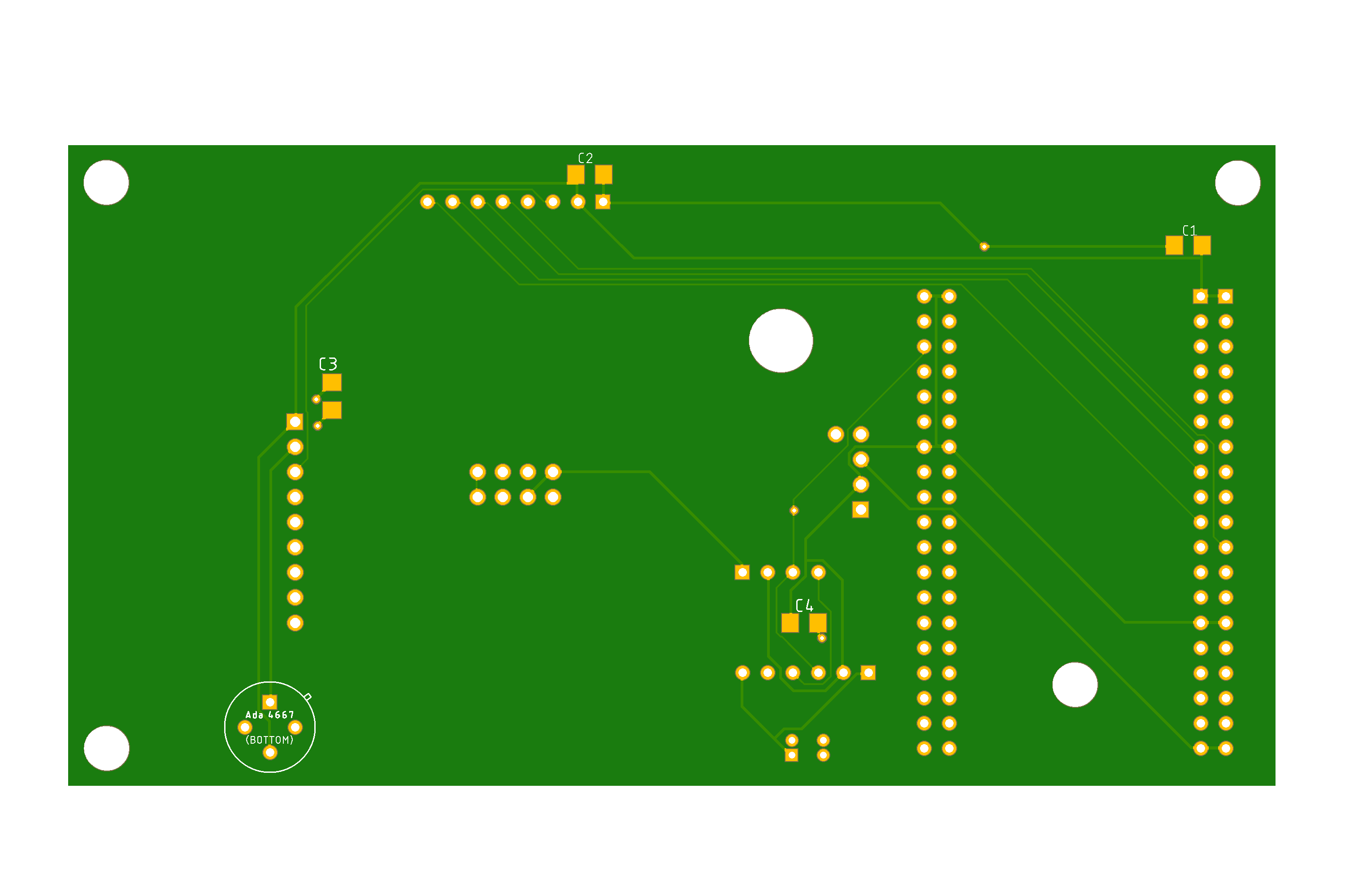
v6.0 ESP32 (DOIT ESP32 DevKit-C v4): Schematic, Board Layout, PCB Top and Bottom
Demo of Breadboard Prototype & Fabricated Board with SH110x OLED Displays Demo of Fab'd Board with IPS TFT Colour Display
Overview: An ESP32 development unit measures temperature, humidity and barometric pressure which it displays on a mono OLED or colour IPS TFT display when nearby motion is detected, otherwise it writes the stats to a micro SD disk every minute. Additionally, WiFi MAC address and status as well as IP address are displayed. A highly accurate USB-based voltmeter is attached to the fab'd PCB. In the beginning of the OLED video it registers about 21mA, of which 12mA are due to powering the two tiny voltmeters in the breadboard. The low value of less than 10mA is when the ESP32 is in Deep Sleep mode. Once it wakes up the current draw is about 100mA with both the OLED display and micro SD being powered. Current needs are higher with the colour IPS display but still appreciably small to aid battery life.
Components: v6.0: DOIT ESP32 DevKit-C v4 with AliExpress_2.0" Colour IPS_Display or 1.3" OLED_Display
Arduino Code: Mono OLED Display: BME280_OLED_RGB_SNTP_SD_PIR_Sleep_5.ino Colour IPS Display: _Stats_Server_ST7789.ino Note: If your ESP32 ever locks up, try this code: Reset_ESP32.ino
The next revision will feature the board acting as a web server to view the stats. |
|
HOW DOES IT ALL WORK? We have designed a PCB to accommodate a number of devices. If you wish to learn how things work while assembling the PCB then I suggest you get yourself a quality breadboard, jumper wires and follow the directions below. Note that this verbiage is for the code (BME280_OLED_RGB_SNTP_SD_PIR_Sleep_5.ino) written for the mono OLED display. The colour IPS display code ( _Stats_Server_ST7789.ino) is very similar but new features have been added. The PCB will contain the
following:
We'll start off by testing
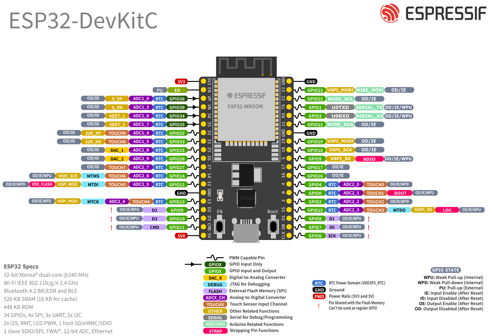
the I2C Devices: If you install two rows of 19-pin sockets (or a
single
38-pin double socket
or cheaper
40-pin double socket) for each side of the ESP32, you can
connect it via the spare pin sockets to a breadboard: the 38-pin
ESP32 is too wide to be used on a standard breadboard. SCL on the ESP32 is pin 22 and SDA is pin 21. If the two I2C devices you're using are designed "properly", they already contain pullup resistors on SCL and SDA. All of these type of sensors I have looked at had SMT resistors marked as 103 indicating they were 10k. They also had a 100nF noise coupling cap on the power supply pin.
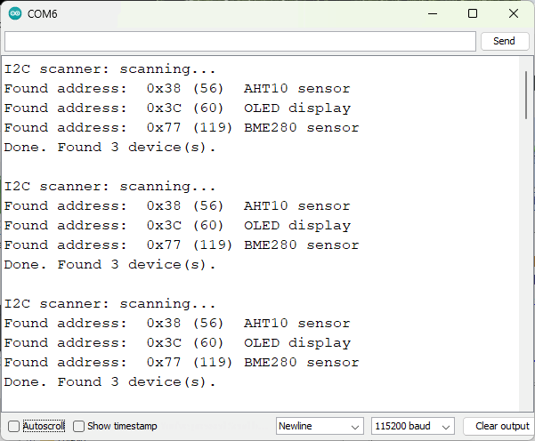
Let's start by checking the I2C address of the
OLED using the Serial Monitor and the scanner sketch
I2C_Scan.ino Remove the BME280 sensor and install the AHT10 sensor. Run the scanner sketch again. - AHT10 I2C address is 0x38 If you install all 3 devices, you should be able to see them all listed in the Serial Monitor as shown here. If one of the devices tested separately is not showing up, consider changing to one of the alternative I2C addresses. For the BME280 that could be 0x76 instead of 0x77. I2C is now tested.
OLED is now tested.
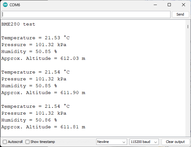
Remove the OLED, install the BME280 sensor, load and run the sketch, BME280_Test.ino. Results can be seen in the serial monitor and here.
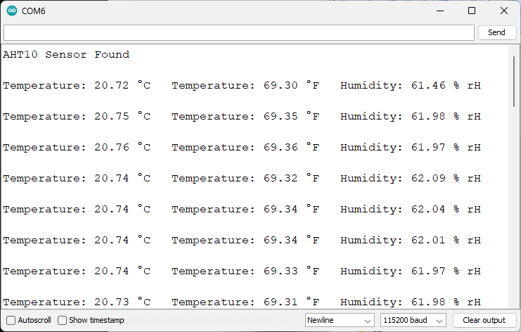
Remove the BME280, install the AHT10 sensor,
load and run the sketch,
AHT10_Test.ino. Results can be seen in the serial monitor
and here. Your sensors are now tested.
We have separately tested the OLED display and
the BME280 or AHT10 sensors, so now let's test them at the same
time. Load up and run the sketch
BME280_OLED.ino
An example from the Serial Monitor can be found here. The RGB LED is now tested.
Troubleshooting: Now that it has stabilized close RGB.ino, upload and run OLED_BME_RGB.ino again. Make sure SM is running before you start the upload to the ESP32.
BME_OLED_RGB_Time.ino is our next sketch.
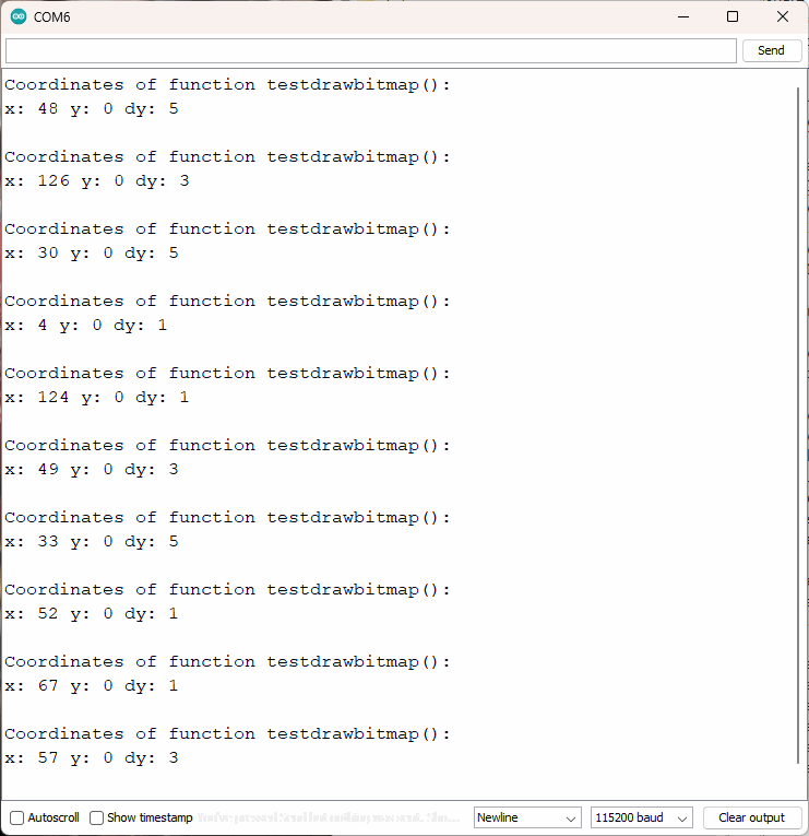
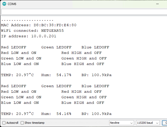
Here is an example
of it working on the Serial Monitor. - The next function EthIP displays both the WiFi MAC and IP addresses on both the OLED and SM - In the next function, RGBLEDs_Off(), the three RGB LEDs are turned off. - In the final function, RGBLEDs_OnOff(), the three LED colours are cycled on and off The local Time function is now tested.
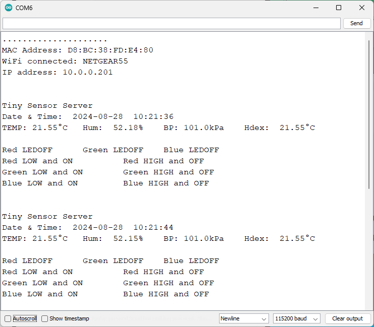
BME280_OLED_RGB_SNTP.ino contains all of the previous code. Code has been added so that the network time protocol (SNTP protocol) is used to accurately update the current time. Here is an example of it working on the Serial Monitor. The following lines were added: - 29 to 32: drivers, time zone and daylight savings time offset - 95 to 100: Can get IP address from DHCP server or the others configured in configTime(). When current time is updated via SNTP, another function timeavailable() can run. It is found in lines 221 to 223. ConfigTime() specifies offset from UTC/GMT, daylight savings time, and two NTP time servers. Lines 36 and 99 accomplish the same thing - 105: function netTimeOLED() of lines 208 to 219 is called which displays the time in the Serial Monitor and on the OLED after clearing it The SNTP network time function is now tested.
BME280_OLED_RGB_SNTP_SD.ino contains additional SD drive code. You MUST use the ESP32 SD and FS drivers or expect trouble during compilation. The driver set can be found here: https://github.com/espressif/arduino-esp32 Info on installing the Arduino-ESP32 support files is found here: NOTE: You may already have SD and FS libraries on your PC located in: 1) C:\Program Files (x86)\Arduino\libraries 2) C:\Users\Your_Name\AppData\Local\Arduino15\libraries 3) C:\Users\Your_Name\Documents\Arduino\libraries Personally, I moved them to private folders, zipped them up and moved them away from the Arduino IDE. This way only the ESP32 drivers will be used. Some of the code related to displaying the date and time has been cleaned up so the line numbers in BME280_OLED_RGB_SNTP_SD.ino won't be the same as our earlier file, BME280_OLED_RGB_SNTP.ino .
Code changes for the SD drive are listed below: - Lines 22 to 25 define the SD drivers and file system drivers needed to run the micro SD card drive - Lines 106 to 115 start the SD drive with the ESP32 DevKit-C v4 specific pins - Lines 290 to 304 contains a list of the File System calls for the SD drive. The calls or functions follow. - In loop() most of the code is the same but line 258 contains the data as a numerical string, e.g., 2024.09.07,16:01:02. This will make it easier to log the temperature/humidity/BP on the SD drive
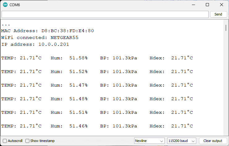
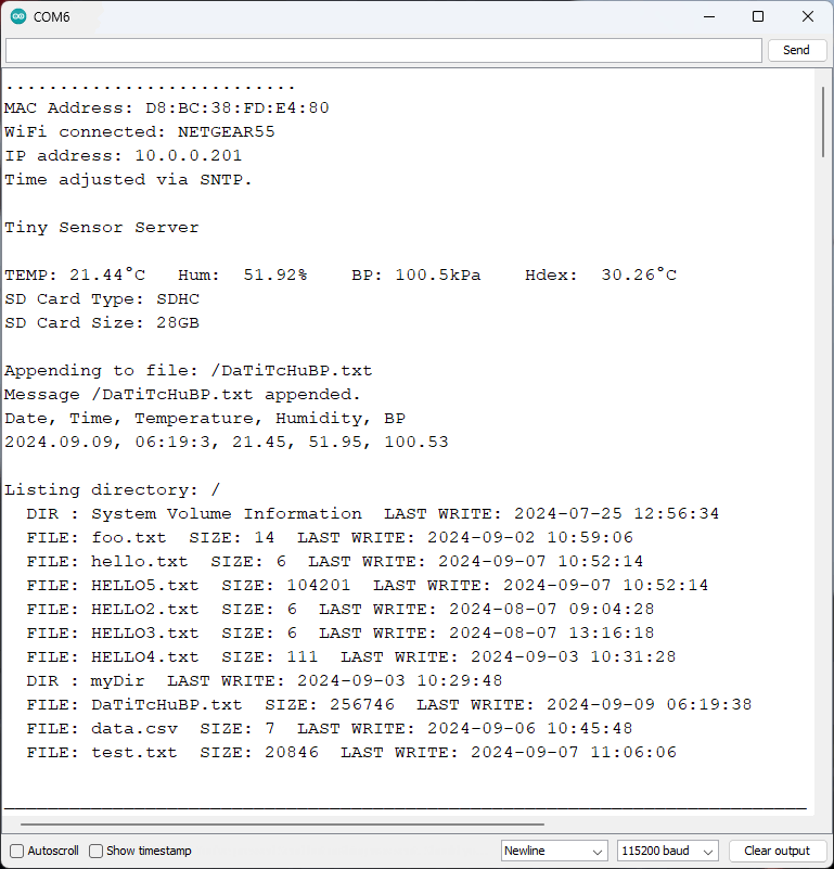
String Formatting (BME280_OLED_RGB_SNTP_SD.ino ) This was the first time I have worked with formatting time to be used as a string that could be written as a line of data to an SD drive. The line numbers involved in the procedure start with line 215 in the function Line5SD(). I used http://gemini.google.com/app to get hints on how to manipulate time data to a character string. I listed the two web links on line 225. The comments that follow the code should hopefully be helpful. Here is an example of it working on the Serial Monitor. The micro SD drive is now tested.
PIR Motion Sensor: The program we have been building is ready to go except that the OLED display is always on which means the power needed to run the display will drain the LiPo battery too soon. If we only turn the display on for a short time when there is movement nearby, then the battery should last a lot longer. Open the test file, monPIR.ino and ensure the LEDs' connection to the ESP32 match those of code lines 10 to 12, and that the PIR pin connection matches the code in line line 17. Run the program with the Serial Monitor active. Move your hand near the PIR and you should see the Serial Monitor output change and the RGB LEDs flash; the flashing should cease after 9 seconds if there is no further movement. The next step will be to integrate most of this code into our main program.
Integrating monPIR.ino into BME280_OLED_RGB_SNTP_SD_PIR_2.ino requires a few changes. They are: - Lines 41 and 42 define the PIR device and its initial operational state - Lines 44 to 56 are used to measure how long the OLED is lit, and the time interval between SD writes to disk - Line 105 defines the PIR as an input. The pin is pulled low by default with the directive "INPUT_PULLDOWN" - Line 144, the main loop() function, contains only one line: "monPIR();" which is short for "monitor PIR". It determines if there is nearby activity in order to light up the display. It also ensures measurements are taken every two seconds and written to disk every one minute. Both of these parameters can be easily changed There are 5 comparison components of monPIR(): - Part 0: Display the amount of time the OLED has been lit, and the total elapsed time since the last disk write. - Parts 1 & 2: Measure activity to determine if the PIR is activated - Part 3: The PIR indicates there is activity. The RGB is flashed, the OLED is lit only long enough for viewing, and the current stats (Date, Time, Tc, Hu, BP) are written to the SD disk - Part 4: The PIR indicates there is activity and that it's time to turn off the OLED - Part 5: A time interval (1 minute) has been reached so whether there is activity or not the stats are written to the SD disk. The PIR motion sensor is now tested.
If we wish to conserve battery power then we should make use of ESP32's Deep Sleep function. This eBook contains a good chapter on the subject. On a separate breadboard we'll setup an ESP32 with GPIO pin 33 connected to a button switch and GPIO pin 25 connected to a 3v3 PIR motion sensor. One side of the button switch should be connected to ground via a 10k resistor and the other side to 3v3 power. The GPIO pin is connected between the resistor and the switch. Load and run the demo file, ExternalWakeUpMultiple_3.ino. Make note of the current time. With Arduino's Serial Monitor (SM) running, place your finger near the button switch and don't move. You should see several instances of the PIR (that detects movement) firing on pin 25. Slowly move your finger to push the button switch and with any luck you won't trigger the PIR again. When you press the push button, the SM should report the the completion of the electrical circuit so the signal level to pin 29 should change from a low to a high; this will be reflected as GPIO waking up the ESP32. When 60 seconds have elapsed since the microcontroller was reset or downloaded, the timer will expire and SM will report the wakeup was caused by the timer expiring. Then the system will return to deep sleep.
Now to implement Deep Sleep: Our sketch, BME280_OLED_RGB_SNTP_SD_PIR_Sleep_5.ino, has been modified a fair amount to accommodate the ESP32 sleep function. The PIR motion detector is connected to GPIO pin 25. When there is motion, the ESP32 system wakes up and starts displaying the weather stats on the OLED or IPS display. Once finished it returns to deep sleep. After a predetermined time (30s for testing, 10 minutes normally) the system wakes up and writes the stats to the SD disk, then returns to Deep Sleep. Current draw during Deep Sleep in less than 10mA. I'll know the exact value when my USB tester arrives next week. Key points in the sketch: - line 73 shows the real time clock (RTC) driver being loaded so that the GPIO pin activity can be read while in deep sleep. - line 75 indicates the GPIO wake up pin will be 25 attached to the PIR - line 76 defines the wake up time. It's set to 30s for testing, otherwise it will be set for 10 minutes (600s). The system will wakeup in line 202 of the code and perform the tasks outlined in line 204 before going back to deep sleep in line 209 - line 81: EXT1 permits one or more GPIO wakeups. Originally we set this up for a PIR and a button switch as inputs but now it is just a PIR on GPIO25. We kept the same command line: GPIO25 or GPIO25 will cause an external wakeup for category EXT1. - line 82: prefix of "RTC_DATA_ATTR" allows the data to be saved in non-volatile storage between boots - line 84 works with line 76 for the time wakeup - line 85: we're working with deep sleep and not light sleep so we'll set the parameter to TRUE otherwise it will be light sleep Two functions were added: - lines 95 to 100 prints the GPIO number that triggered the wakeup - lines 102 to 133 prints the wakeup reason - lines 157 to 167: startup WiFi and print the Connect Status. If it fails to startup, Disconnect WiFi and try again. Continue this process until WiFi is successfully started and ESP32 is connected - line 188: increment the ESP32 boot counter. Because the count is kept in EEPROM, it will continue to increment with each reboot - line 190: display the wakeup reason - line 191: these are the parameters for setting the wakeup type: bitmask specifies the GPIO pins, EXT1 indicates more than one pin, wakeup when any of the GPIO pins in the bitmask go high - line 193 to 194: the PIR is normally low and goes high when activated so we enable a pulldown resistor and disable a pullup resistor - lines 196 to 202: these are our normal display functions for the current weather: they will execute and then the sleep timer will start. It is based on the value set in line 76 - line 204: save the stats to the SD card - line 207: Espressif recommends flushing the Serial Monitor buffer before sleep - line 209: and now Deep Sleep starts. Nothing else will execute - Loop() is blank. If GPIO25 goes high from detecting motion OR the sleep timer (set to 30s when testing, 10 minutes otherwise) expires, then the system will wakeup but it will appear as if the ESP32 is booting up and the entire sketch will run again WiFi Status: Lines 224 to 254 will give us all state conditions for the WiFi. Ideally, we want to see condition "3, WL_CONNECTED" but recognize that problems can occur. The code in lines 157 to 167 handle that situation.
Final Note: This configuration allows the ESP32 to boot, take and display measurements, then save them to disk. It is not yet been configured as a server so that remote measurements can be taken. The WiFi Server mode would be enabled in line 92.
|
![]()
![]()
Updated 2024-10-17 @ 8am